Peter Björk, Bilfinger, explores selective catalytic reduction technology to address stricter control requirements
This article will explain the scientific backgrounds, advantages, and possibilities of selective catalytic reduction (SCR). The increased focus on environmental aspects and efforts to make the world an overall cleaner place, has made the EU set new stricter standards for NOx emissions for industry in general. Measures must therefore be taken by the cement industry. Appropriate systems must be applied to reduce the NOx and ammonia-slip levels in gas emissions, in order to stay below the new maximum limits of 200 mg/Nm3 NOx and 30 mg/Nm3 NH3. Of all the available solutions, SCR is the preferred and most common technology applied and, at present, is considered state-of-the-art technology.
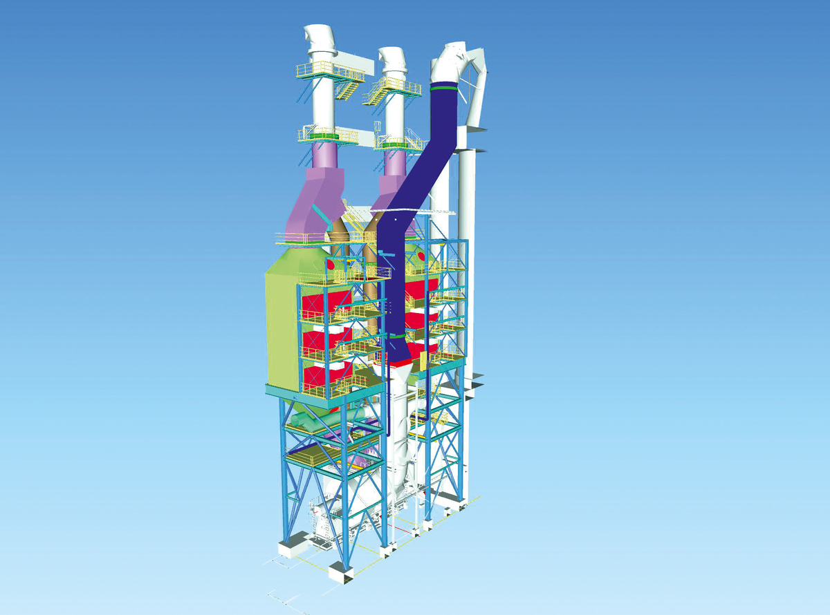
Double-string high dust SCR solution.
In the SCR process, the nitrous gases NO and N02 are eliminated from the flue gas by injecting a reducing agent, e.g. ammonia or urea, into the gas. The gas is channelled through a specific catalyst in which the nitrous gases and the ammonia are converted into nitrogen and water vapour. The SCR reactor can be configured to either allow high dust or low dust processes - determined from the position of the reactor being up-stream or down-stream to the main filter. Both solutions ensure reliable compliance with the allowed maximum limits.
Functional description
Chemical reactions
Catalytic flue gas cleaning helps to reduce the emission of NOx by using the SCR process.
In this process, the nitrous gases react with the reducing agent, typically and in this case ammonia, as shown in the following simplified chemical equations:
4 NO + 4 NH3 + O2 → cat 4 N2 + 6 H2O
6 NO2 + 8 NH3 → cat 7 N2 + 12 H2O
NO + NO2 + 2 NH3 → cat 2 N2 + 3 H2O
While the gas is flowing through the catalyst, nearly all of the NH3 added (to keep up with the required efficiency rate) will react with the NOx. A small amount of NH3, however, will not react. This is called the ammonia-slip. The ammonia-slip is controlled and reduced by either selecting the corresponding catalyst or by optimising operational conditions such as flow rate, gas temperature, and distribution of NH/NOx upstream of the catalyst.
A small part of the SO2 contained in the flue gas is oxidised, as shown in the following chemical equation:
2 SO2 + O2 → 2 SO3
This reaction must be avoided to the greatest extent possible in order to avoid the formation of ammonium bisulfate and ammonium sulfate.
NH3 + SO3 + H2O → NH4HSO4
2 NH3 + SO3 + H2O → (NH4)2SO4
The formation of these salts depends on the content of SO3 and NH3, as well as on the temperature of the flue gas; if they condensate, this may clog and reduce the flow area and deactivate the catalyst. For this reason, the catalyst must be operated above a certain minimum temperature.
DeNOx control concept
In order to determine the necessary amount of reducing agent, both the NOx load as given at the entrance of the SCR reactor and the clean gas NOx value to be obtained need to be identified. The NOx load is determined in what is known as a feed-forward control system using the measured concentration of NOx and the volume of raw gas. lt is not necessary to measure NO2. An adjustment factor is applied, based on the assumption that the flue gas contains 95% NO and 5% NO2.
The difference between the measured concentrations of NOx raw gas and of clean gas serves as the basis for determining the necessary NOx efficiency rate. NOx efficiency rate, together with the NOx load of the raw gas, the known concentration of the ammonia water, and the stoichiometric ratio of NH3 and NOx that is needed, represent the fundamental parameters to identifying the quantity of ammonia water that is called for.
In addition, a feed-back control system is integrated into the ammonia quantity control system. For this purpose, the clean gas concentration of NOx having been achieved is compared to the target value. In the event of any deviations, the set point in the feed-forward control system is adjusted accordingly.
SCR-DeNOx system
In the high dust configuration, the SCR DeNOx system is integrated into the cement production cycle directly downstream of the preheater. The catalyst reactor is typically installed alongside the preheater. The reducing agent is injected into the flue-gas stream at a sufficient distance upstream of the SCR reactor, to ensure proper mixing of the reducing agent in the gas flow. The flue gas then runs through the SCR reactor from top to bottom. The inflow of gas into the reactor is routed and controlled to ensure even distribution of the gas across the catalyst layers. Baffle plates and a flow rectifier minimise pressure lass while ensuring that distribution of flue gas and flow across the catalyst layers remain uniform.
The catalysts are delivered as modules. They are arranged in the SCR reactor in levels or layers. The volume and composition of the flue gas, the required NOx efficiency rate, the targeted ammonia-slip, and the required operating life and operating temperature range of the SCR system constitute the main parameters used to select the catalyst type and catalyst capacity to be installed. The reactor's inlet is linked with the outlet of the preheater. The connecting duct also contains a cooling system to control the gas temperature going to the SCR reactor.
The configuration of the SCR reactor includes a certain number of catalyst layers to make the complete system compliant with the required emission limits. An additional reserve level may, however, be provided. This may be required at a later point in time if a stricter NOx emission limit is introduced, but they are typically used to optimise the consumption of catalyst elements and thus reduce the operational cost (catalyst management), ensuring that catalyst layers are close to complete de-activation before being replaced. Catalyst management is also applied to obtain Operation of the SCR reactor through a full production campaign. Dust blowers, driven by compressed air, are installed above each layer of catalysts. Redundancy in the compressor system secures that dust blowers are always operational, keeping catalyst layers clean, and that emission limits are met.
The relevant measuring technology, both upstream and downstream of the reactor, is included in the design. The configuration includes a dust discharge unit offering a heated funnel, rotary air lock, and screw conveyor. A by-pass duct allows the gas to be directed straight to the filter.
DeNOx reactor
The reactor housing consists of several support levels. The top level contains the flow straightener, while the catalyst elements are located on the lower levels. These grid levels allow work to be performed safely and quickly, both when the catalyst is installed and when replacing catalyst layers. Service doors are provided at every level of the catalysts layers, to allow the elements to be introduced into the reactor. Moreover, manholes are available at every level to ensure that the reactor can be entered above the catalyst levels during a system shut-down.
The guide plates, which are mounted inside the inlet duct, work together with the flow straightener to distribute the flue gas over the cross-section of catalysts and to ensure an even and vertical flow through the catalyst layer. The dimensioning of the reactor takes account of various parameters, such as volumetric flow rate, height of the catalyst elements, and optimisation of pressure lass. The reactor's cross-section does not depend on the catalyst manufacturer selected, or the respective type of catalyst.
In order to comply with the requirements, a necessary number of reactor levels are equipped with catalyst elements. The design of the system allows analytical measurements to be performed upstream and downstream of the reactor, as weil as temperature and pressure measurements. An additional sensor grid for analysing the gas is located at the reactor outlet below the lowermost of the catalyst levels. The sensor grid allows the injection of the reducing agent to be fine-tuned to create a homogeneous distribution between NH3 and gas, thus keeping the ammonia-slip at the lowest possible level. This prolongs the life of the catalyst.
Major technical challenges are posed by the operating conditions that prevail for catalysts in cement plants with high dust concentrations in the flue gas. This is where experience and technological capabilities are applied: when engineering the solution to meet specific requirements. The main parameters to address include the following:
- The technically appropriate selection and dimensioning of catalysts.
- Appropriate and efficient adjustability of process temperatures.
- Optimal flow and dispersion of flue gas over the entire cross-section of the reactor.
- Extremely low pressure lasses across the entire SCR reactor.
- An efficient catalyst cleaning system with a minimum consumption of compressed air.
- Precise measuring and control of the NOx concentrations of raw gas and clean gas.
- Lang catalyst lifetime without unscheduled disruptions to production.
- Low service and maintenance costs.
- An operationally tried-and-tested catalyst management that exploits catalyst performance and reduces operating costs.
At present, a high dust double-string SCR system with a capacity of 200 000Nm3/hour is under construction in Germany. The project is being designed, planned, commissioned, and executed completely by Bilfinger.
About the author
Peter Björk is Director of Cement, Strategic Business Development at Bilfinger.